The Direct Leakage Method:
The Direct Leakage Method is identical to the method used in the IEC 60601-1 standard, measuring the true leakage through a body model (MD) to earth (See Figures 1 and 2).
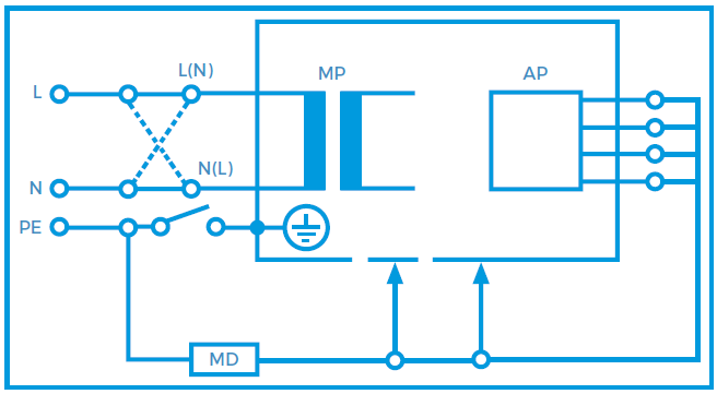
Figure 1. Equipment leakage direct - Class I
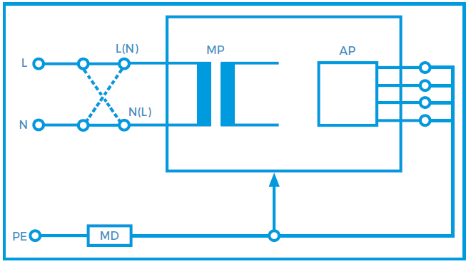
Figure 2. Equipment leakage direct – Class II
Benefits
• Measures the true leakage on operational devices
• Means of measuring both AC and DC leakage current
• Highest accuracy compared to other methods
• Potential leakage through a human body via measuring device
• Direct comparison with measurements made in accordance with IEC 60601-1
Considerations
• The 1KΩ resistors forming the Measuring Device is interrupting the low resistance earth conductor thus causing potential hazard when testing faulty equipment.
• Secondary earth path(s). The EUT / DUT must be positioned electrically isolated from earth during the measurement. A lower leakage might be measured as not all leakage is measurable in the earth conductor.
• Secondary connections are typical with:
• Equipment bolted to steel enforced concrete floor (eg dentist chairs, MRI)
• Equipment connected to gas or water supply
• Equipment part of a Medical Electrical System
• Equipment connected to PC / Printer
• A difference in Polarity of the Live and Neutral conductors might alter the leakage readings, as such leakage measurements must be done in each polarity of mains supply
• A TN (Terre –Neutral) system is required to ensure that the measurements are done at maximum Live to Earth voltage. Any voltage between Neutral and Earth might result in a lower reading, potentially passing faulty equipment.
The Differential Leakage method:
The Differential Leakage Method measures the leakage current as a result of imbalance in current between the Live conductor and the Neutral conductor (See Figures 3 and 4). Potential secondary earth connections are included in the total measurement and as such, the EUT doesn’t require to be positioned isolated from earth. Low leakage currents of less than 75μA are difficult to measure using the Differential Leakage method. As such the Differential Leakage method is deemed unsuitable for measuring conductive unearthed parts and in those instances where leakages are expected to be below 75μA.
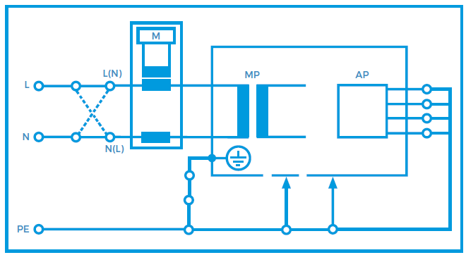
Figure 3. Equipment leakage differential - Class I
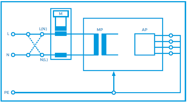
Figure 4. Equipment leakage differential - Class II
Benefits
• The measurements are not influenced by secondary earth connectionsIt measures the total equipment leakage current.
• The measuring device (1KΩ resistor) is no longer in series with the earth conductor, thus providing a low resistance protective earth.
Considerations
• The Differential Leakage measurement is less suitable to accurately measure lower leakage currents. (<100μA)
• The measurements are influenced by external magnetic field or the analyser’s own internal magnetic fields caused current frequency and high current consumption of the DUT.
• A difference in Polarity of the Live and Neutral conductors might alter the leakage readings, as such leakage measurements must be done in each polarity of mains supply
• Both Direct and Alternative methods provide higher accuracy and better frequency range required for measuring trends in low leakage conditions.
The Alternative Leakage method:
The Alternative Method is in effect similar to testing the leakage current to IEC 60601 whilst measuring with the Open Neutral single fault condition in both polarities at once. Other comparison can be made with the Insulation test method (except, we do not measure resistance at a DC voltage but leakage at 50Hz) and the Dielectric Strength Test at mains potential, using a current limited voltage source at mains frequency. The Live and Neutral conductor are shortened together and the current limited voltage is applied between the mains parts and other parts of the equipment. Due the current limiting resistor(s), the actual measuring voltage is dependent on the test load. As such, the measured leakage current should be calculated to the linear proportionate value at the mains voltage.
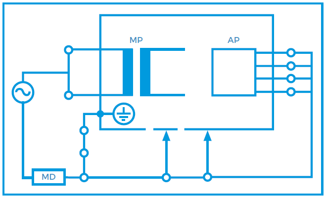
Figure 5. Equipment leakage alternative - Class I
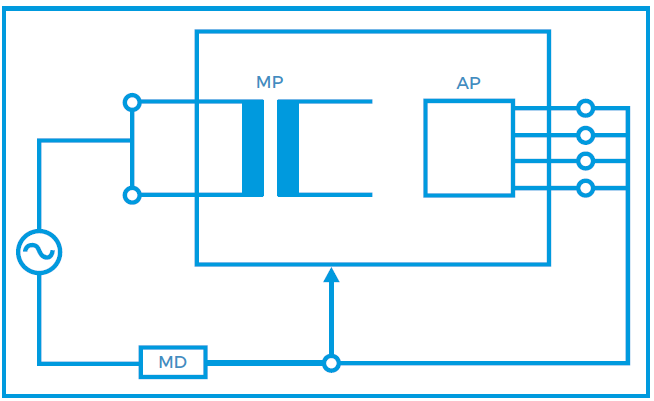
Figure 6. Equipment leakage alternative - Class II
Benefits
• As live and Neutral are combined, the mains polarity has no influence. Only one measurement is required.
• Fast and effective open neutral testing at both polarities at once (save time)
• In comparison with the 500VDC insulation test, the Alternative Leakage test resembles the true leakage behaviour at 50Hzs mains potential prior to switching on the equipment.
• The DUT is disconnected from mains thus providing a high level of safety for the test engineer.
• TN-System is not required due to mains free application.
• Measurements are not influenced by secondary earth connections.
• Tests can be performed from a battery powered instrument.
• Measurements are highly repeatable and provide a good indication of deterioration in the dielectrics of the medical device under test.
Considerations
• Active circuits will not be activated thus prohibiting the actual leakage currents on this type of equipment.
• The Alternative Method is only comparable with the IEC 60601 open neutral SFC test results.


Sign up to our Newsletter.
Stay up to date with the latest industry and product news, as well as our free educational content such as webinars and our expert guides.
Close