This guide will take you through the steps required to upload a Power Reference Curve to the Rigel Med-eBase software for use when creating a test sequence for the Rigel Uni-Therm Electrosurgical Analyser.
Equipment required:
- PC with Med-eBase software
- Reference Graph
Note: You will require two reference curves, one for the upper limit and one for the lower limits for each specific device
Create Reference Curve
1) Open the file ‘RefGraphtemplateMB.csv’ which accompanied this document as a download fromRigelmedical.com. Please
see the example below also:
[REFGRAPH],
Graph Name,
10,
100,1100,
200,1200,
300,1300,
400,1400,
500,1500,
600,1600,
700,1700,
800,1800,
900,1900,
1000,2000,
[END],
Note: One comma is required at the end of every line and between numbers. Therefore when the curve is created in excel please reopen the curve in notepad (or similar) to check locations of commas is correct.
2) [REFGRAPH] and [END] must remain at the beginning and end of the file.
3) Graph Name is the name of the reference curve and can be changed. This will be the name of the graph which will be shown once imported into Med-eBase.
4) 10 is the number of points on the graph, this can be changed but the lines of data must reflect this number.
5) Column A in excel should be the X axis, and represents the Load (). Column B is the Y axis and represents the Power (W). In this example line 3 is a plot of 100Wat 100. In Excel commas are not required but please check they are visible in notepad/word format.
6) Once you have completed plotting the point in the CSV file, Select File and then Save As. Save the file with a recognisable name and .txt extension, e.g. GraphName.txt.
7) A Rename message may appear as you have changed the file extensive from csv to txt.
Note If the rename message does not appear you may need to switch on the document extensions to complete this action. To do this, go to My Computer and select Organise and then Folder and Search Options. Then go to the view tab and un-tick hide extensions for known files type
***PLEASE GO BACK AND RE-TICK THIS FIELD once the action is completed***
Uploading Ref Graph to Med-eBase
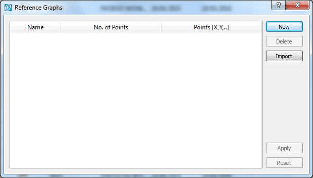
8) Open Med-eBase software and go to Tools > Reference Graph…
9) Once in the Reference Graph menu select Import and then locate and select the txt file previously created. Once selected press Save on the window

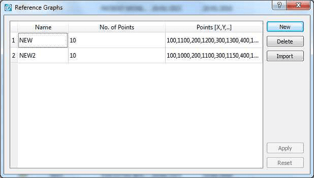
10) The graph should now be shown in the main window of the Reference Graph menu with the title you indicted in the far left name filed, the number of points and the {x,y] positions.
11) Select apply to save the graph into Med-eBase
Note: You will need to import an Upper and Lower graph for each device/test.
Using your Uploaded Reference Graph
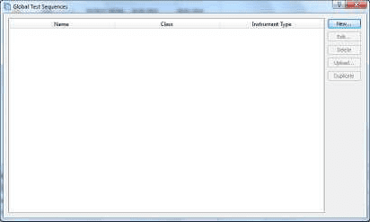
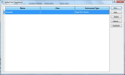
1) To use the uploaded Reference Curve go to Tools > Global Test Sequences
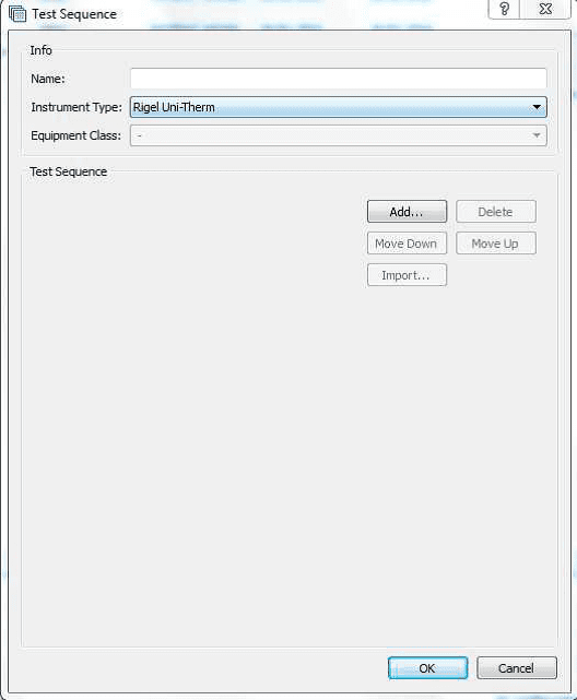
2) Select New > Select the instrument type Uni-Therm and give the test sequence a name.
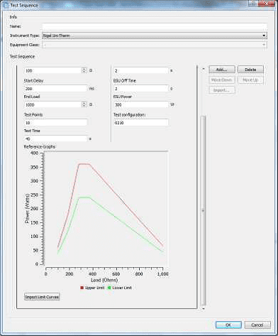
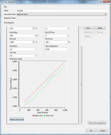
3) Then go to Add > select Graph Power Test. You can then open and change the settings for this test by pressing the icon.
This includes inserting a custom Upper and Lower Reference Graph by selecting Import Limit Curves
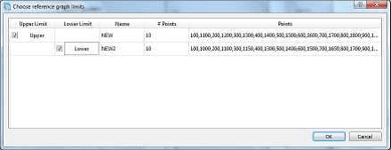
4) Insert a custom Upper and Lower Reference Graph by selecting Import Limit Curves. Select the Upper and Lower limit and then select Ok.
5) The limits will then appear on the Power Curve.
6) Once selected select OK and then Ok to close the test sequence window.
7) The test sequence can then be uploaded on the Rigel Uni-Therm and the test sequence selected to test.
Uploading the sequence onto the Rigel Uni-Therm
1) Connect the USB A/B lead between the Rigel Uni-Therm and PC.
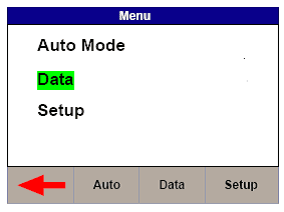
2) On the Rigel Uni-Therm select F1 Menu then F3 Data.
3) Select F2 OPERATION to indicate Import Test Sequence and select F3 PORT to select USB PC Connection. Alternatively you can use a USB memory stick and select USB memory stick as the PORT selection.
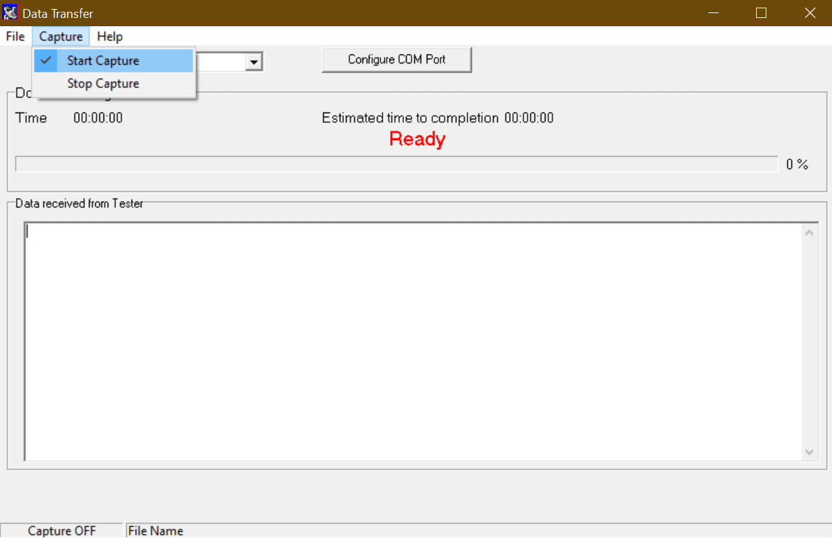
4) Select Start when you are ready to receive the test sequence file from Med-eBase. Then DO NOT select OK!
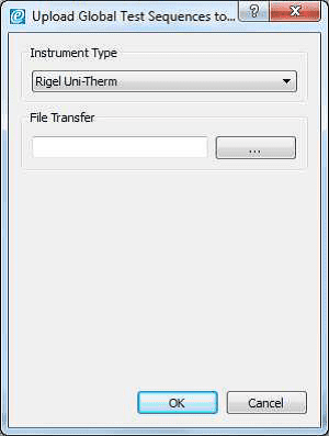
5) On the PC open Med-eBase go to Tools > Global Test Sequences. Highlight the sequence and then select upload.
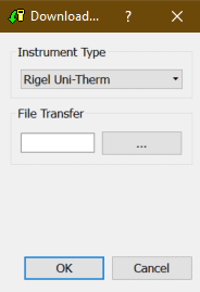
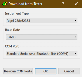
6) The Instrument type should be Uni-Therm and then select …
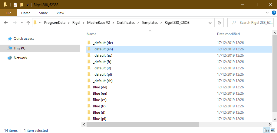
12) Select the removable drive that has now appeared for the Uni-Therm. Make sure the file name is Sequences_X.sss (X can be any given name).
13) Select save and then on the upload screen OK.
14) Then on the Uni-Therm select OK to complete the IMPORT.