Electrical Safety Testing FAQs
Advice and support for users of Rigel’s electrical safety analyzers
Get the most out of your Rigel electrical safety analyzers and find the answers to your questions with our FAQs.
How do I safety test equipment sensitive to power breaks, such as PC based equipment?
When testing ME Equipment using an Automatic Safety Analyser, it is important that measurements are taken once the Device Under Test is fully operational and all parts of the device are active. To ensure this condition, the safety analyser must first power-up the DUT and delay the measurements until the right conditions are met.
The Rigel 288+ and Rigel 62353+ have unique Semi-Automatic Modes that allows the user to manually control the power-up and power-down as well as manually starting the automatic test sequences once the DUT is fully operational. This means that not only the correct measurements are made but also ensures that the Rigel 288+ and Rigel 62353+ provides sufficient time to power-down any device which is sensitive to improper power-breaks e.g. Ultrasound equipment and PC based ME Equipment.
Another feature of the Rigel 288+and Rigel 62353+ is the grouping of Single Fault Conditions which result in only two power-ups. This will significantly reduce test times on equipment with a long start-up time such as Dialysis and Imaging Equipment.
What is the difference between Macroshock and Microshock?
There are two distinct types of electrocution which need to be considered in healthcare environments: macro-shock and micro-shock.
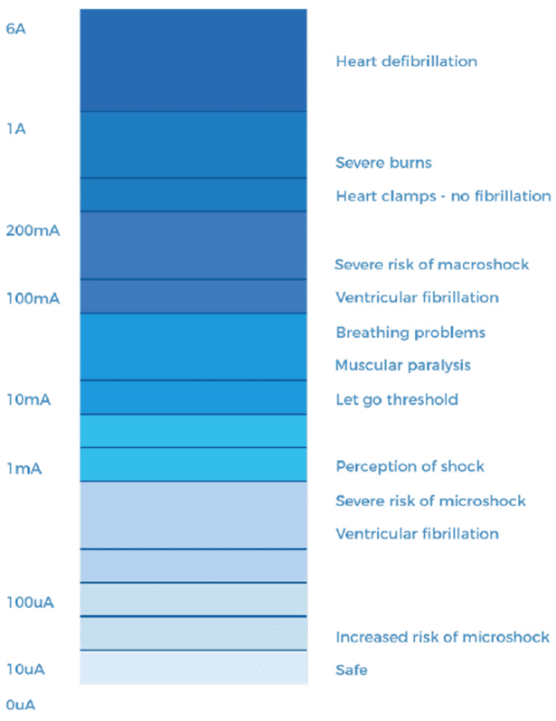
Macro-shock occurs when current passes through the body via contact with the skin and this aspect applies to all types of electrical safety. However, external dry skin has high resistance, which limits current flow through the body. Many medical procedures involve moistening the skin, which lowers skin resistance significantly, such as ultrasound gel and surgical applicants. Furthermore, patients are often in constant physical contact with medical electrical (ME) equipment, both directly and indirectly e.g., electrical monitoring systems and electrically powered beds. The results from macro-shock lead to loss of voluntary muscle control at currents as low as 10mA and ventricular fibrillation at currents of approximately 100mA.
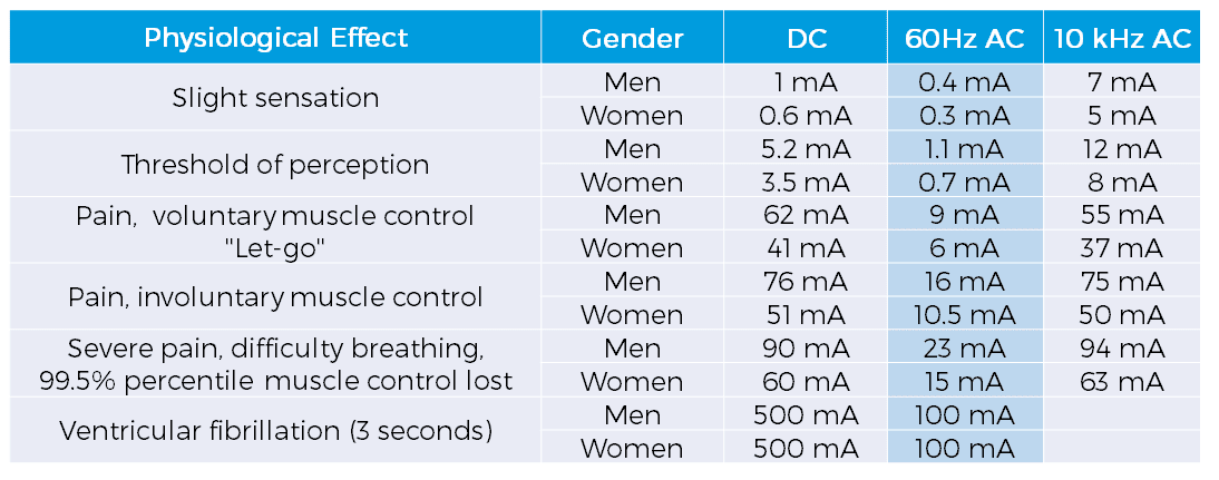
Micro-shocks occur when invasive patient connections are placed across or in close proximity to myocardial tissue and nerves and blood components have relatively low resistance. Therefore, very small levels of electrical current can induce ventricular fibrillation because tissue impedance below the skin surface is low and current is focussed at an invasive location. Death by micro-shock is known as micro-electrocution and both catheters and pacemakers carry this risk. It has been repeatedly estimated that currents of over 20 microamps can lead to micro-electrocution. Patients in medical environments are uniquely vulnerable to the risks from micro-shock.
Several corresponding studies have recognised the physiological effects of electrical current under macro-shock and micro-shock conditions, and international standards reflect these results in their safety criteria. In 1971 “Ralph Nader’s Most Shocking Exposé,” revealed that about 1,200 people a year were dying in hospitals from the effects of micro-shock. Several years later, in 1977, the safety standard IEC 60601 was formed and parts of it have survived to this day. Further developments and revisions have led to year on year reductions in death from both macro and micro-electrocution.
Which leakage test should I use for my test?
When selecting a leakage test during your electrical safety testing, select the correct leakage test by asking the following questions:
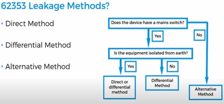
An brief explination of Direct leakage, Differential leakage and Alternative leakage
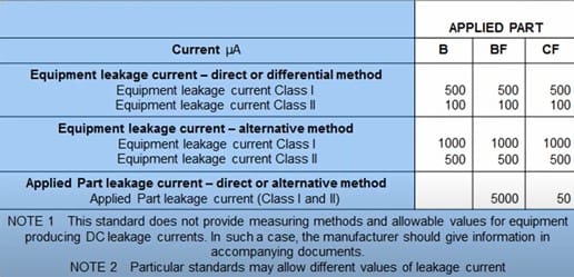
IEC 62353 Leakage Limits
Can I carry out safety tests on an isolated (IT) supply or non-TN system?
Incorrect readings could occur when testing on either an IT, Missing, Centre Tab or Split Rail Supply. When considering the test environment according to IEC 60601-1-1, the test setup is based on a TN (Terre-neutral) supply, because it ensures the highest possible leakage. Non-TN systems have a lower potential to ground and safety testing carried out on these systems could potentially pass faulty units (See Figure 1).
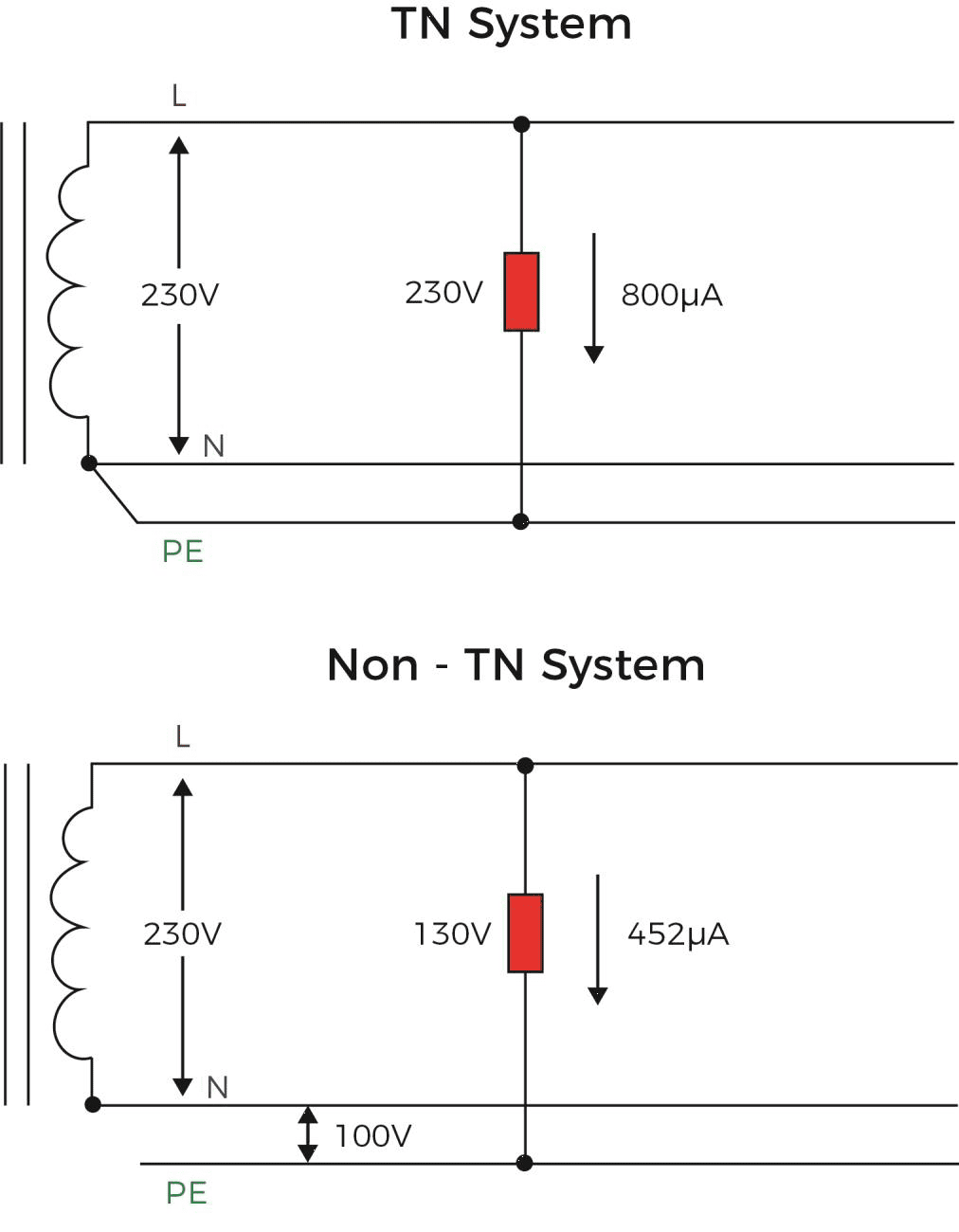
Figure 1: Potential difference and leakage currents on TN and Non-TN systems
Due to the portability of most electrical safety analyser, the products are not supplied with internal isolation transformers. For instance, the Rigel 288+ is rated to power-up and measure on instruments up to 4KVA. Incorporating a 4KVA rated Isolation transformer into our products would add approximately 15 – 25 Kilo’s to the unit’s weight. For obvious reasons, we would no longer class such size and weight as portable hence defeating our objective to produce Portable and Innovative Test Equipment.
In case measurements are done on an IT system we would recommend using a sufficiently rated External Isolation Transformer or using an extension cable powered from a TN supply, to ensure the safety analyser is able to measure the maximum leakage. If this is not possible, the measurements done on an IT system will be considerably lower and considerations must be given to the test results.
The leakage current measurements in the IEC 60601-1 are described and referred to, using the full mains potential between L and E. Any voltage between N and E would result in a difference between the full mains potential (L-N) and the L – E potential thus resulting in incorrect readings. All Rigel electrical safety analysers do however; provide a warning to the user in case of a missing Earth or when the voltage between Neutral and Earth exceeds 4 Volts, as shown in Figure 2. The latter would indicate that the L – E voltage is no longer equal to the L-N voltage.
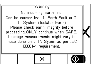
Figure 2. Warning message for potential non-TN system
If it is imperative leakage measurements are taken with the tester powered from an IT mains system, the equipment under test will only be valid for that condition. When medical equipment is then moved outside an IT system, further testing should be provided to determine the true leakage at a TN system.
For traceability while testing on an IT supply, automatic test sequences using the Rigel 288+ and 62353+ provide a comment that is automatically added into the SAVE TEST RESULTS screen. This comment states “IT Supply – Confirm Correct Measurements”. This comment may be deleted if required.
Why perform electrical safety tests?
Electrical safety testing ensures medical equipment (ME) is electrically safe for use in a healthcare environment by testing for breakdown or damage. Medical device safety testing is more stringent when compared with generic electrical devices. Patients are significantly exposed to electrical hazards as they are connected directly to electrical devices. During medical procedures intra-cardiac electrical connections are also present, whereby low leakage currents could cause ventricular fibrillation.
When looking at electrical leakages of medical devices, there are two types of potential electrical shocks to be considered; macroshock and microshock. Macroshock is an electrical current applied externally (between an electrical source and the skin) and is dispersed over a larger surface area than microshock. Ventricular fibrillation (VF) of the heart occurs around 100mA. Microshock occurs when current flows directly through the myocardium via intra-cardiac connections e.g., pacemakers or saline catheters. Current density is much larger and close to myocardial tissue so VF can occur between 20 and 100 μA (Over 100 times less than macroshock!).
To ensure patient safety, leakage limits reflect these potential hazards. Furthermore, applied parts are classified into different classifications:
• Type B (Body) – Non-invasive. Earth Reference e.g., hospital bed
• Type BF – Non-invasive, patient circuit floating type e.g., defibrillator paddle
• Type CF – Invasive, cardiac. Patient circuit floating type e.g., pacemaker, ECG module
In the 3rd edition of IEC 60601-1 leakage limits under normal fault conditions vary significantly (Earth leakage - 5000μA, patient leakage (DC) - 10 μA, patient leakage (AC) - 100 μA). There are additional fault conditions provided in medical safety testing to adhere to the stringent parameters. For instance, on F-type tests (BF and CF) a fault condition with mains on applied part is produced.
What are the definitions and symbols commonly used in IEC 60601 and IEC 62353?
Equipment Under Test - The equipment (EUT) which is the subject of testing.
Device Under Test - The device (DUT) which is the subject of testing.
Applied Part - Part of the medical equipment, which is designed to come into physical contact with the patient, or parts that are likely to be brought into contact with the patient.
Patient Connection - Individual physical connections and / or metal parts intended for connection with the patient, which form (part of) an Applied Part.
Patient Environment - Volumetric area in which a patient can come into contact with medical equipment or contact can occur between other persons touching medical equipment and the patient, both intentional and unintentional. (see Appendix E)
F-Type Applied Part - Applied Part which is electrically isolated from Earth and other parts of the medical equipment. i.e. floating. F-type Applied Parts are either type BF or type CF Applied Parts.
Type B Applied Part - Applied Part complying with specified requirements for protection against electric shock. Type B Applied Parts are those parts, which are usually Earth referenced. Type B are those parts not suitable for direct cardiac application.
Type BF Applied Part - F Type Applied Part complying with a higher degree of protection against electric shock than type B Applied Parts. Type BF Applied Parts are those parts not suitable for direct cardiac application.
Type CF Applied Part - F Type Applied Part complying with the highest degree of protection against electric shock. Type CF Applied Parts are those parts suitable for direct cardiac application.
Medical Electrical Equipment - Electrical equipment, designed for treatment, monitoring or diagnoses of patients, powered from not more than one connection to mains supply and which are necessarily in physical or electrical contact with the patient or transfers energy to or from the patient or detects such energy transfer to or from the patient.
Medical Electrical System - Combination of equipment of which at least one is classed as medical electrical equipment and as such specified by the manufacturer to be connected by functional connection or use of a multiple portable socket-outlet.
Class I - Equipment protection against electric shock by (earthed) additional protection to basic insulation through means of connecting exposed conductive parts to the protective Earth in the fixed wiring of the installation.
Class II - Also referred to as Double Insulated. Equipment protection against electric shock by additional protection to basic insulation through means of supplementary insulation are provided, there being no provision for the connection of exposed metalwork of the equipment to a protective conductor and no reliance upon precautions to be taken in the fixed wiring of the installation.
Commonly used symbols and markings in IEC 60601 and IEC 62353:
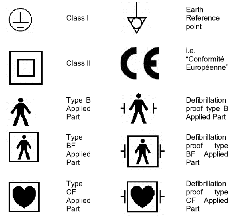
Figure 1: Commonly used symbols and markings
What are the different leakage current methods in IEC 62353?
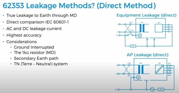
The Direct Leakage Method:
The Direct Leakage Method is identical to the method used in the IEC 60601-1 standard, measuring the true leakage through a body model (MD) to earth (See Figures 1 and 2).
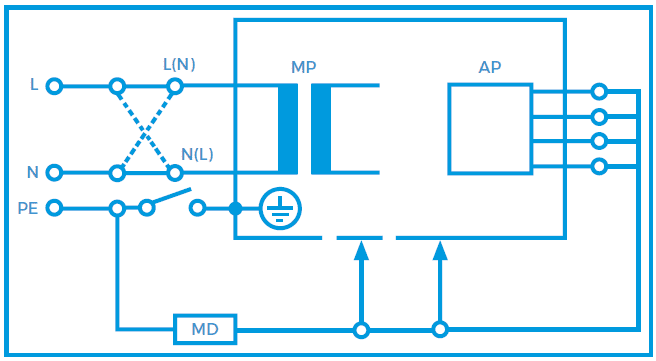
Figure 1. Equipment leakage direct - Class I
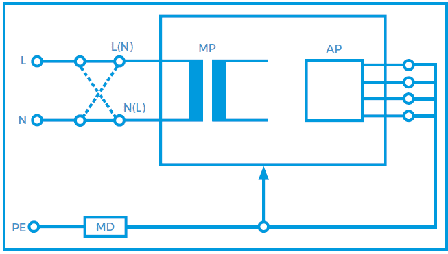
Figure 2. Equipment leakage direct – Class II
Benefits
• Measures the true leakage on operational devices
• Means of measuring both AC and DC leakage current
• Highest accuracy compared to other methods
• Potential leakage through a human body via measuring device
• Direct comparison with measurements made in accordance with IEC 60601-1
Considerations
• The 1KΩ resistors forming the Measuring Device is interrupting the low resistance earth conductor thus causing potential hazard when testing faulty equipment.
• Secondary earth path(s). The EUT / DUT must be positioned electrically isolated from earth during the measurement. A lower leakage might be measured as not all leakage is measurable in the earth conductor.
• Secondary connections are typical with:
• Equipment bolted to steel enforced concrete floor (eg dentist chairs, MRI)
• Equipment connected to gas or water supply
• Equipment part of a Medical Electrical System
• Equipment connected to PC / Printer
• A difference in Polarity of the Live and Neutral conductors might alter the leakage readings, as such leakage measurements must be done in each polarity of mains supply
• A TN (Terre –Neutral) system is required to ensure that the measurements are done at maximum Live to Earth voltage. Any voltage between Neutral and Earth might result in a lower reading, potentially passing faulty equipment.
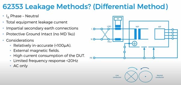
The Differential Leakage method:
The Differential Leakage Method measures the leakage current as a result of imbalance in current between the Live conductor and the Neutral conductor (See Figures 3 and 4). Potential secondary earth connections are included in the total measurement and as such, the EUT doesn’t require to be positioned isolated from earth. Low leakage currents of less than 75μA are difficult to measure using the Differential Leakage method. As such the Differential Leakage method is deemed unsuitable for measuring conductive unearthed parts and in those instances where leakages are expected to be below 75μA.
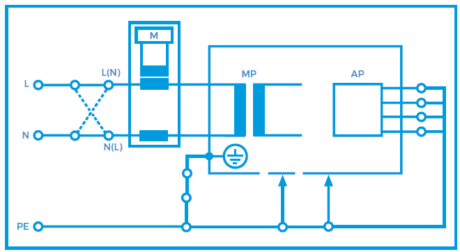
Figure 3. Equipment leakage differential - Class I
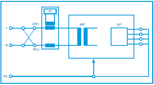
Figure 4. Equipment leakage differential - Class II
Benefits
• The measurements are not influenced by secondary earth connectionsIt measures the total equipment leakage current.
• The measuring device (1KΩ resistor) is no longer in series with the earth conductor, thus providing a low resistance protective earth.
Considerations
• The Differential Leakage measurement is less suitable to accurately measure lower leakage currents. (<100μA)
• The measurements are influenced by external magnetic field or the analyser’s own internal magnetic fields caused current frequency and high current consumption of the DUT.
• A difference in Polarity of the Live and Neutral conductors might alter the leakage readings, as such leakage measurements must be done in each polarity of mains supply
• Both Direct and Alternative methods provide higher accuracy and better frequency range required for measuring trends in low leakage conditions.
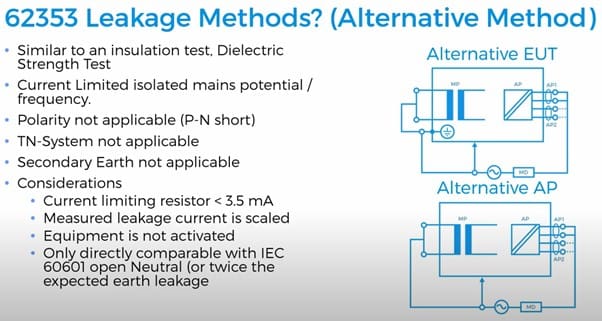
The Alternative Leakage method:
The Alternative Method is in effect similar to testing the leakage current to IEC 60601 whilst measuring with the Open Neutral single fault condition in both polarities at once. Other comparison can be made with the Insulation test method (except, we do not measure resistance at a DC voltage but leakage at 50Hz) and the Dielectric Strength Test at mains potential, using a current limited voltage source at mains frequency. The Live and Neutral conductor are shortened together and the current limited voltage is applied between the mains parts and other parts of the equipment. Due the current limiting resistor(s), the actual measuring voltage is dependent on the test load. As such, the measured leakage current should be calculated to the linear proportionate value at the mains voltage.
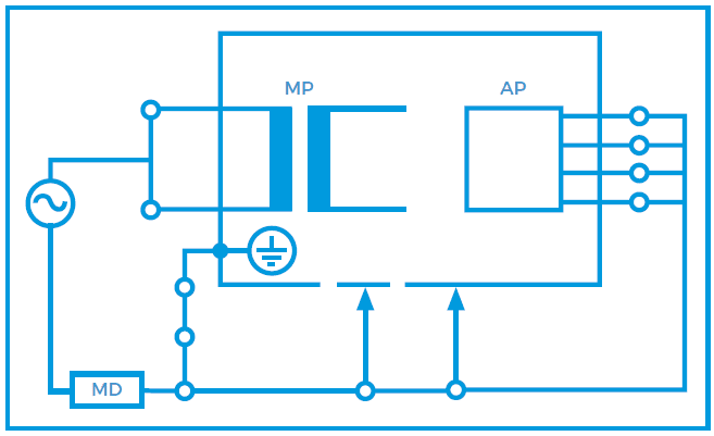
Figure 5. Equipment leakage alternative - Class I
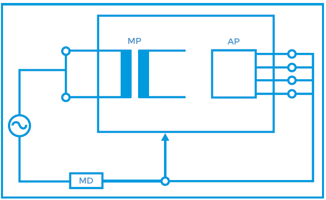
Figure 6. Equipment leakage alternative - Class II
Benefits
• As live and Neutral are combined, the mains polarity has no influence. Only one measurement is required.
• Fast and effective open neutral testing at both polarities at once (save time)
• In comparison with the 500VDC insulation test, the Alternative Leakage test resembles the true leakage behaviour at 50Hzs mains potential prior to switching on the equipment.
• The DUT is disconnected from mains thus providing a high level of safety for the test engineer.
• TN-System is not required due to mains free application.
• Measurements are not influenced by secondary earth connections.
• Tests can be performed from a battery powered instrument.
• Measurements are highly repeatable and provide a good indication of deterioration in the dielectrics of the medical device under test.
Considerations
• Active circuits will not be activated thus prohibiting the actual leakage currents on this type of equipment.
• The Alternative Method is only comparable with the IEC 60601 open neutral SFC test results.
How to perform electrical safety tests?
Medical electrical safety analysers are developed with measurement circuits to simulate typical impedance and electrical characteristics of the human body. These circuits are referred to as a Body Model and are specified in electrical safety standards, including IEC 60601-1 and 62353.
Leakage tests are performed by measuring leakage currents using the body model. There are various methods depending on the standard but all leakage measurements are performed from different points on a device under normal and fault conditions. Both IEC 60601-1 and 62353 require leakage tests to be performed in a variety of fault conditions e.g., earth open, neutral open, and reverse supply.
Protective earth testing is provided by measuring the resistance between the equipment under test (EUT) earth and an exposed conductive part of the enclosure. This ensures there is a low resistance current path for any potential fault currents to flow back to earth and not through the patient or user. This test is only carried out on class 1 devices as class 2 uses double insulation as its supplementary form of protection.
What are secondary earth paths?
Secondary earth paths are a common problem, but often go unnoticed during medical electrical safety testing.
Because electrical currents follow the path of least resistance, it is important to realise that secondary earth path connections could influence the measurements of leakage currents. Secondary connections are typical with:
Compared to the 1kΩ resistance of the body model, a secondary earth path will be substantially lower (~1Ω). As such, electrical currents are almost entirely flowing down the secondary earth path, away from the measurement circuit of the safety analyser, as shown in the figures below, which represent an example of a secondary earth connection via a data cable.
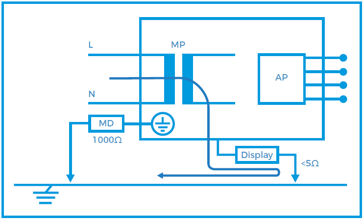
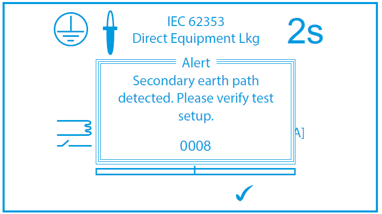
This will result in a zero reading on the safety analyser and could potentially pass a dangerous medical device. In case a secondary earth path exists, the Rigel safety analysers will provide the user with an error message.
If the secondary earth paths cannot be removed, one should revert to the differential leakage method in IEC 62353, which can measure the total leakage even when a secondary earth path exists. This is because the differential leakage method does not rely on a 1kΩ body model.
What is electrical safety testing?
Safety testing ensures the safety of clinicians, visitors or patients who may come in contact with any electrical devices. It is always part of preventative maintenance procedures and is developed to prevent danger to anyone from electric shock. The international standard, IEC 60601-1, states the safety requirements for manufacturers of medical devices but this standard has also been adapted for routine testing of medical devices. However, in-service, recurrent and post repair standards have been developed specifically for a unified approach to routine testing, such as IEC 62353.
Electrical equipment powered by mains are classified into two different types of protection; either Class 1 (earthed) or Class 2 (double insulated). Medical devices are required to have supplementary protection to ensure adequate electrical isolation from any applied parts. Patient protection is classified as B (Body), BF (body floating) or CF (cardiac floating) and all medical devices are required to be labelled with a classification.
Electrical safety of medical devices according to international standards falls into four primary tests:
• Earth bond/continuity – Protective earth is the primary form of protection for class 1 devices. It provides a low resistance path incase of leakage or fault currents. Safety testing ensures a low resistance earth path exists.
• Leakage tests (Enclosure/Earth) – Ensures current leakage from equipment falls within a specified limit.
• Patient leakage tests – Ensures current leakage from any applied parts falls within a specified limit (A higher degree of isolation is required for patient connections within medical devices and the specified current limits are much lower than other leakage tests)
How do I test on fixed or 3-phase equipment?
When testing fixed wired or 3-phase equipment, a number of safety tests can be carried out by powering the safety analyser from a normal mains supply provided this is at the same earth reference as the fixed wired equipment (single or three phase).
Point to point earth bond tests can be carried out for fixed and three phase equipment using the setup shown in Figure 1. The earth bond resistance measurement is between the chassis of the device under test (DUT) and a common earth point. As an added feature, the Rigel 288+ and 62353+ are battery operable for this particular test.
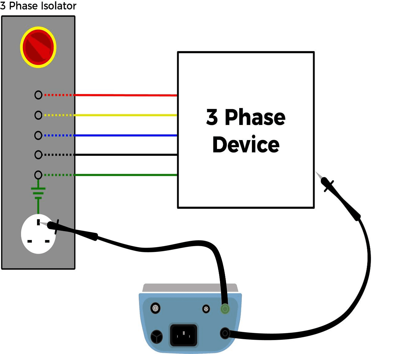
Figure 1. Point to point earth bond test on three-phase equipment
The leakage test setup is shown in Figure 2 and the safety analyser must be plugged in. The tests to be operated are according to the standard used. IEC 60601 tests include enclosure leakage, patient leakage, patient auxiliary leakage and mains on applied parts leakage. IEC 62353 tests include direct leakage and applied parts leakage.
Due to the fixed connection of the device under test (DUT), the safety analyser is not able to measure earth leakage; nor will the safety analyser be able to measure under single fault conditions (unless the earth and neutral are physically interrupted at the switch board or mains panel). To measure Earth Leakage, a current clamp can be used provided the earth wire is separated from the Live and Neutral wires.
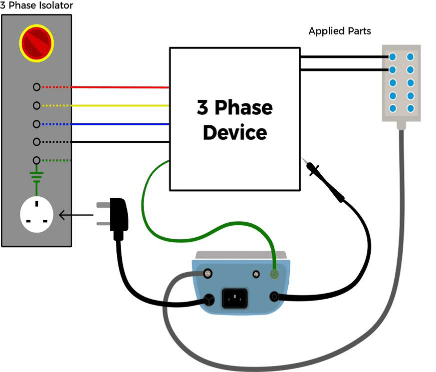
Figure 2. Leakage testing setup for three-phase equipment
Be aware of Secondary Earth Connections
Be aware that some fixed wired equipment is bolted into the floor which might cause an external earth path. The Rigel 288+ and Rigel 62353+ will warn for secondary earth connections should this happen (See Figure 3). To follow the correct IEC 60601-1 requirements, the fixed wired equipment would have to be disconnected from the mains however, this is not considered a practical option. Therefore, testing following the suggestions above would ensure the DUT is electrically safe.
When in doubt, always refer to the manufacturers recommendations.
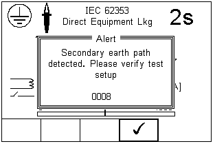
Figure 3. Rigel 288+/62353+ secondary earth path warning
What are leakage currents?
According to IEC 60601, leakage current is any current that is not functional. Any current that flows from the intended circuit to earth, the chassis or other conductive parts is considered to be leakage current. It is unavoidable due to stray capacitive and resistive dielectrics but is considered non-hazardous if limits are within the IEC 60601 design criteria.
In a Class I Earth Leakage example below, leakage current travels down the earth path to ground within a medical device. In a standard TN system, current in the live wire carries both the functional current and leakage current, whereas the neutral wire contains only the functional current.
Earth leakage (IL) can be expressed as: I1 (L current) – I2 (N current)
All mains powered equipment is developed to ensure safe levels of leakage current are achieved. Earth and enclosure type leakage currents have limits that reflect the values associated with macro-shock. Medical electrical (ME) equipment is designed to have even higher degrees of isolation due to the introduction of patient applied parts and the risks associated with micro-electrocution (See: Microshock and Macroshock). Patient and user operator safety is crucial under both normal and single fault (NFC and SFC) conditions.
Leakage current measurements can also often be easily overlooked and subject to incorrect testing (See: Testing on TN and Non-TN Systems and Secondary Earth Paths).
How do I carry out safety tests on battery powered equipment?
Battery operated equipment is often defined as class III equipment. The term class III is referred to in some standards as medical equipment (ME) that is powered from safety extra low voltage (SELV); which is defined as voltage not exceeding 25V AC or 60V DC. However, class III is not formally used or recognised in the IEC 60601-1 standard and states that voltage limitations are not satisfactory in ensuring patient safety.
For safety testing, battery powered equipment is split into two categories; externally powered and internally powered.
Externally powered ME is supplied by a mains charger or adaptor. These should be treated and tested as class I or class II as applicable using a Rigel 288+/62353+. The earth on externally powered ME is a ‘functional’ earth and not a protective earth, so earth bond readings can be up to 1Ω.
Internally powered ME has no mains connection. The IEC 60601-1 standard requires touch current leakage tests between parts of the enclosure, not between enclosure and earth (See Figure 1). Please note: only The Rigel 288+ can do point to point leakage tests. For further information, please refer to section 5.12. ‘Point to Point Enclosure Leakage Test (battery powered)’ in the Rigel 288+ manual.
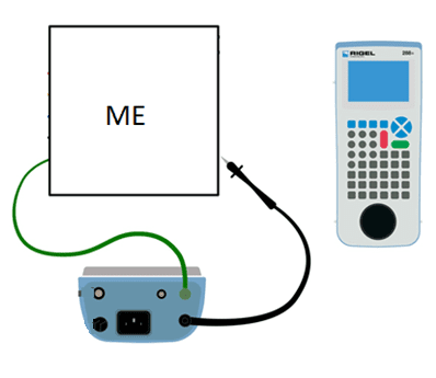
Figure 1: Point-to-point leakage tests on internally powered ME with the Rigel 288+
The IEC 62353 standard only requires applied part direct method testing, which can be carried out by the Rigel 288+ and 62353+. The method requires measuring leakage from all applied parts on internally powered equipment to any conductive or nonconductive parts on the enclosure. Please see Figure 2 for the set up.
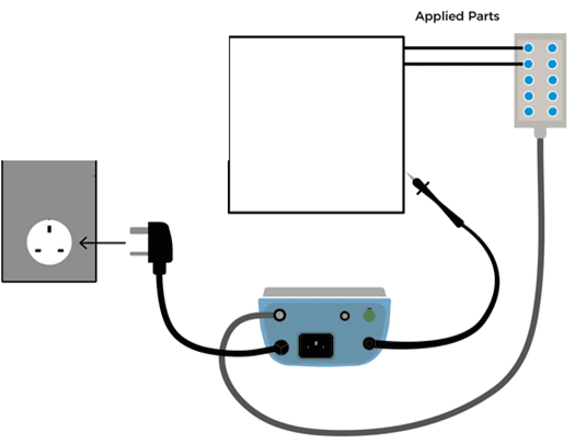
Figure 2: Direct method applied part leakage testing on internally powered ME
How do I test class I equipment with no exposed conductive parts?
There may be instances where class 1 equipment has no exposed earthed metal parts, which makes the earth continuity test impossible to carry out.
The device under test cannot be tested as Class II equipment. The test should be carried out as normal but the earth continuity test should be emitted, and then a supporting comment recorded in the results. The duty holder must then alter the risk assessment relating to this item.
The manufacturer will always remain the ultimate authority on testing its products so can seek guidance from the manufacturer.
Sign up to our mailing list today to stay up to date with the latest industry news and information from Seaward.

Contact us
Email: sales@rigelmedical.com
Switchboard: +44 (0) 191 586 3511
Phone: +44 (0) 191 587 8730